GRE over IPsec Configuration
Introduction
Generic Routing Encapsulation (GRE) is a tunneling protocol developed by Cisco Systems. It allows the encapsulation of a wide variety of network layer protocols inside virtual point-to-point or point-to-multipoint links over an Internet Protocol (IP) network. GRE encapsulates different types of network layer protocols and creates a virtual IP tunnel for the transmission of multiple protocols.
GRE is often used in conjunction with IPsec VPN to encapsulate routing information and provide data encryption. The benefits of GRE technology include extending existing networks over the internet, integrating legacy systems, and supporting multicast traffic between two networks.
This article provides an example of how to configure GRE over IPsec functionality on D-Link M2M routers.
Please note that this example is based on specific prerequisites and topology. D-Link does not guarantee the compatibility with all third party platforms or clients.
Prerequisites
1. 2 x M2M devices: The IPsec feature is applicable to the following models:
- DWM-313, DWM-530-T, DWM-550-G, DOM-550-TSO, DOM-550-GSO, DTM-550-G
- The WAN access of both devices must have a static global IP.
Please note that this prerequisite assumes both sites are Internet accessible.
Topology
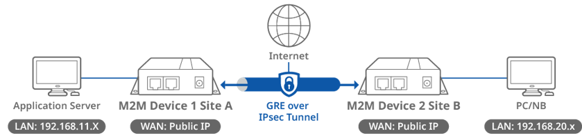
This topology diagram illustrates a GRE over IPsec VPN scenario. Both D-Link M2M devices at Site A and B have a static public IP address on its WAN interface. The application server can be any multicast service that responds to the subscriber from the remote sites.
Before starting GRE over IPsec configuration, please make sure the basic network setting of the D-Link M2M device is configured properly.
Device 1 GRE Configuration (Site A)
GRE Configuration
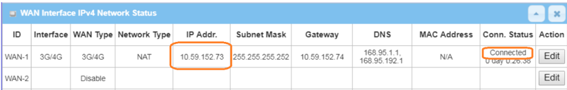
1. Before GRE configuration, please check the WAN interface status and make sure the M2M router/gateway WAN interface has already obtained a public IP address.
Go to Status > Basic Network > WAN & Uplink tab
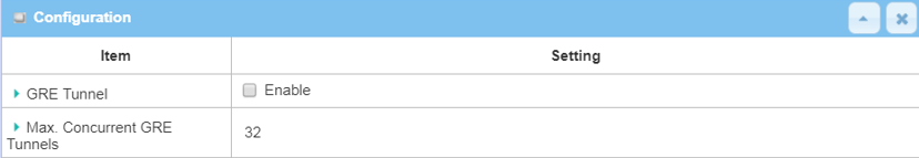
2. Go to Security > VPN > GRE tab
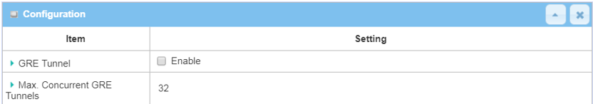
Please note that the specification of Max. Concurrent GRE Tunnels varies across different D-Link M2M devices.
| Item | Description |
|---|---|
| GRE Tunnel | Check the Enable box to activate the GRE tunnel |
| Save | Click the Save button to save the settings |
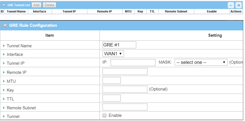
3. Click the Add button of the GRE Tunnel List to create GRE policy for Site B.
| Item | Description |
|---|---|
| Tunnel Name | Enter a tunnel name |
| Interface | Select the available WAN interface on which the GRE tunnel is to be established |
|
Remote IP |
Enter the Remote IP address of remote GRE tunnel gateway |
| MTU | Enter 1500 value |
| TTL | Enter 255 value |
| Remote Subnet | Specify the Remote Subnet IP address: 192.168.20.0 |
| Tunnel | Check the Enable box to enable this GRE tunnel |
| Save | Click the Save button to save the settings |
Device 2 GRE Configuration (Site B)
GRE Configuration
1. Go to Security > VPN > GRE tab
| Item | Description |
|---|---|
| GRE Tunnel | Check the Enable box to activate the GRE tunnel |
| Save | Click the Save button to save the settings |
2. Click the Add button of the GRE Tunnel List to create a GRE policy for Site B.
| Item | Description |
|---|---|
| Tunnel Name | Enter a tunnel name |
| Interface | Select the available WAN interface on which the GRE tunnel is to be established |
| Remote IP | Enter the Remote IP address of the remote GRE tunnel gateway |
| MTU | Enter 1500 value |
| TTL | Enter 255 value |
| Remote Subnet | Specify the Remote Subnet IP address: 192.168.11.0 |
| Tunnel | Check the Enable box to enable this GRE tunnel |
| Save | Click the Save button to save the settings |
Test Result
Please configure the device according to the above environment, then validate to ensure everything works as expected.
From Device 1 or 2
Go to Basic Network > Routing > Routing Information tab
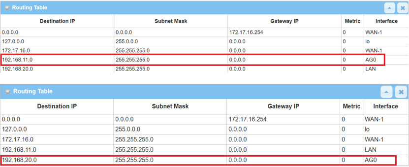
A new route with GRE interface is created on the device for Remote Subnet.
From the client under the device 1 or 2
After the GRE tunnel is established, also test remote access from LAN clients by using ping <Remote LAN interface IP> or < Remote LAN device IP> within the Remote Subnet.
Device 1 IPsec Configuration (Site A)
After configuring the GRE tunnel on both devices, we can proceed to create an IPsec tunnel to achieve the GRE over IPsec application.
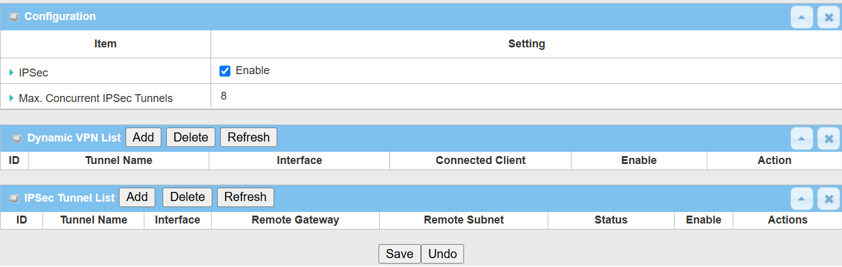
1. Enable IPsec setting: Go to Security > VPN > IPsec tab
Click the Enable box to activate the IPsec setting and click the Save button.
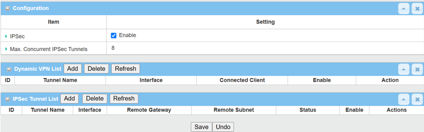
Click the Add button of the IPsec Tunnel List to create an IPsec policy for Site B.
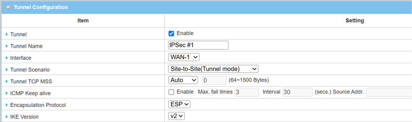
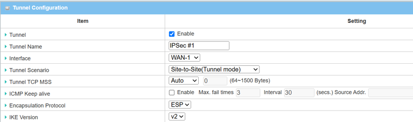
1. The Tunnel Configuration will appear, click the Enable box to enable the IPsec tunnel.
| Item | Description |
|---|---|
| Tunnel | Check the Enable box to activate the IPsec tunnel |
| Tunnel Name | Enter a tunnel name |
|
Interface |
Select the available WAN interface on which the IPsec tunnel is to be established |
| Tunnel Scenario | Select Site-to-Site (Tunnel Mode) from the drop-down menu |
| Tunnel TCP MSS | Select Auto from the drop-down menu |
| ICMP Keep Alive | Leave the Enable box unchecked to disable Keep Alive |
| Encapsulation Protocol | Select ESP from the drop-down menu |
| IKE Version | Select v2 from the drop-down menu |
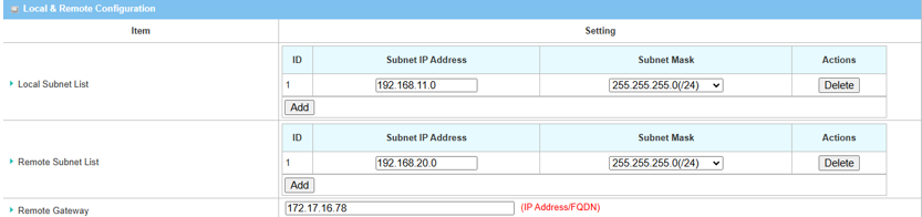
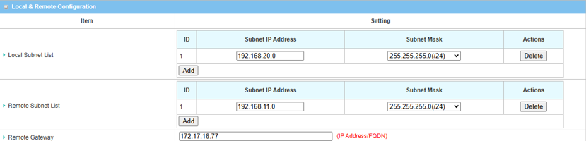
2. Fill in Local & Remote Configuration
| Item | Description |
|---|---|
| Local Subnet List | Specify the local subnet IP address: 192.168.11.0 and Subnet Mask: 255.55.55.0(/24) based on this scenario |
| Remote Subnet List | Specify the Remote Subnet IP address: 192.168.20.0 and Subnet Mask: 255.55.55.0(/24) based on this scenario |
| Remote Gateway | Specify the WAN public IP address of device 2 in site B |
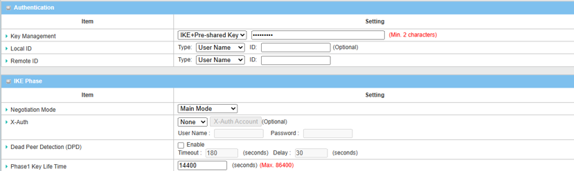
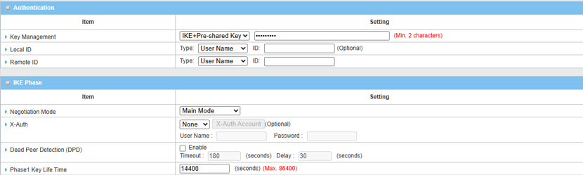
3. Set up Authentication and IKE parameters
| Item | Description |
|---|---|
| Key Management |
Select IKE+Pre-shared Key from the drop-down menu, and fill in the pre-shared key Please note that the pre-shared key must match for both device 1 and 2 |
| Local ID (optional) | Leave it as default setting |
| Remote ID (optional) | Leave it as default setting |
| Negotiation Mode | Select Main Mode from the drop-down menu |
| X-Auth | Select None from the drop-down menu |
| Dead Peer Detection | Uncheck the Enable box to disable DPD |
| Phase1 Key Lifetime | Leave 14400 default setting |
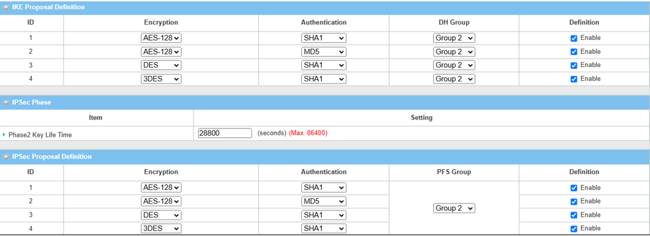
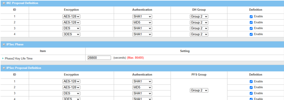
4. Set up Proposal Configuration
Please note that the configuration settings for both Device 1 and Device 2 must match.
| Item | Description |
|---|---|
| IKE Proposal Definition |
Leave the Enable default setting on Web UI Encryption: AES-128 / DES / 3DES Authentication: SHA1 / MD5 DH Group: Group2 |
| Phase2 Key Lifetime | Leave 28800 default setting |
| IPsec Proposal Definition |
Leave the Enable default setting on Web UI Encryption: AES-128 / DES / 3DES Authentication: SHA1 / MD5 PFS Group: Group2 |
| Save | Click the Save button to save the settings |
Device 2 IPsec Configuration (Site B)
1. Enable IPsec setting: Go to Security > VPN > IPsec tab
Click the Enable box to activate the IPsec setting and click the Save button.
Click the Add button of the IPsec Tunnel List to create an IPsec policy for Site A.
2. The Tunnel Configuration will appear, click the Enable box to enable the IPsec tunnel.
| Item | Description |
|---|---|
| Tunnel | Check the Enable box to activate the IPsec tunnel |
| Tunnel Name | Enter a tunnel name |
| Interface | Select the available WAN interface on which the IPsec tunnel is to be established |
| Tunnel Scenario | Select Site-to-Site (Tunnel Mode) from the drop-down menu |
| Tunnel TCP MSS | Select Auto from the drop down menu |
| ICMP Keep Alive | Leave the Enable box unchecked to disable Keep Alive |
| Encapsulation Protocol | Select ESP from the drop-down menu |
| IKE Version | Select v2 from the drop-down menu |
3. Fill in Local & Remote Configuration.
| Item | Description |
|---|---|
| Local Subnet List | Specify the local subnet IP address: 192.168.11.0 and Subnet Mask: 255.55.55.0(/24) based on this scenario |
| Remote Subnet List | Specify the Remote Subnet IP address: 192.168.20.0 and Subnet Mask: 255.55.55.0(/24) based on this scenario |
| Remote Gateway | Specify WAN public IP address of device 1 in site A |
4. Set up the Authentication and IKE parameters.
| Item | Description |
|---|---|
|
Key Management |
Select IKE+Pre-shared Key from the drop-down menu, and fill in the pre-shared key Please note that the pre-shared key must match for both device 1 and 2 |
|
Local ID (optional) |
Leave it as default setting |
| Remote ID (optional) | Leave it as default setting |
| Negotiation Mode | Select Main Mode from the drop-down menu |
| X-Auth | Select None from the drop-down menu |
| Dead Peer Detection | Uncheck the Enable box to disable DPD |
| Phase1 Key Lifetime | Leave 14400 default setting |
5. Set up Proposal Configuration.
Please note that the configuration settings for both Device 1 and Device 2 must match.
| Item | Description |
|---|---|
|
IKE Proposal Definition |
Leave the Enable default setting on Web UI Encryption: AES-128 / DES / 3DES Authentication: SHA1 / MD5 DH Group: Group2 |
|
Phase2 Key Lifetime |
Leave 28800 default setting |
| IPsec Proposal Definition |
Leave the Enable default setting on Web UI Encryption: AES-128 / DES / 3DES Authentication: SHA1 / MD5 PFS Group: Group2 |
| Save | Click the Save button to save the settings |
Test Result
Please configure the device according to the above environment, then validate to ensure everything works as expected.
From Device 1
1. Go to Status > Security > VPN tab
The IPsec Tunnel Status table will display the tunnel information.
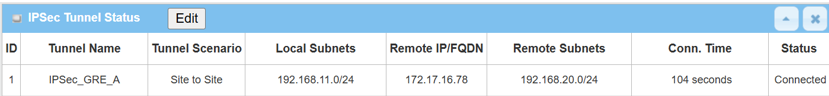
2. Go to Security > VPN > IPsec tab.
The Status of the IPsec Tunnel List displays Connected for Site B Device 2.

From Device 2
1. Go to Status > Security > VPN tab
The IPsec Tunnel Status table will display the tunnel information.
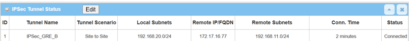
2. Go to Security > VPN > IPsec tab
The Status of the IPsec Tunnel List displays Connected for Site A Device 1.
