Products
ProductsSolutionsApplications
Resources
Introduction
The purpose of digital inputs and outputs is to monitor and control connected devices, or to receive signals from the devices to trigger specific events. In this example, we will show the Digital Input (DI), Digital Output (DO) configuration rules of the M2M DOM Series devices and how to set trigger events to take actions on DO when trigger events come in from the digital input. The DO of the M2M DOM Series products supports Relay Contact and Open Collector. In addition, the DO of the M2M DOM Series products is a dry contact.
Prerequisites
1. DO Type-1 for Relay Contact:
This feature is applicable to the following models:
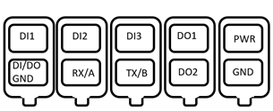
DOM-530-TSO
1 x DI (Isolated, Logic 0: 0~2 V, Logic 1: 5V~30V)
1 x DO (Relay Mode, Max. 30 V/30 W) (TB): External VCC for DO (<30V)
2. DO Type-2 for Open Collector:
This feature is applicable to the following models:
DOM-311-TSO
3. DI (Logic 0: 0~2V, Logic 1: 5V~30V)
2 x DO (Open Collector, Max. 30V/1.25W) (TB): External VCC for DO (<30V)
DOM-550-GSO
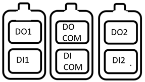
2 x DI (Isolated, “Logic 0”: 0~2V, “Logic 1”: 5V~30V)
2 x DO (Open Collector, Max 24V/7.2W) (TB): External VCC for DO (<24V)
Topology
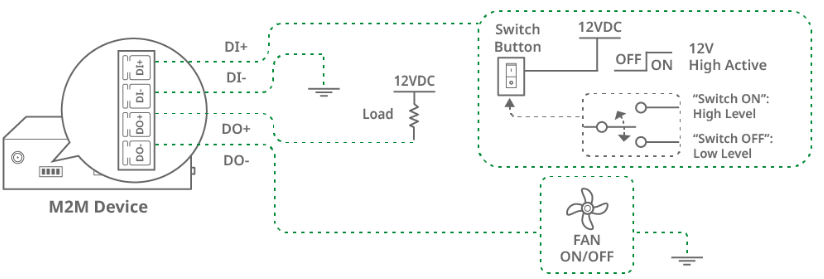
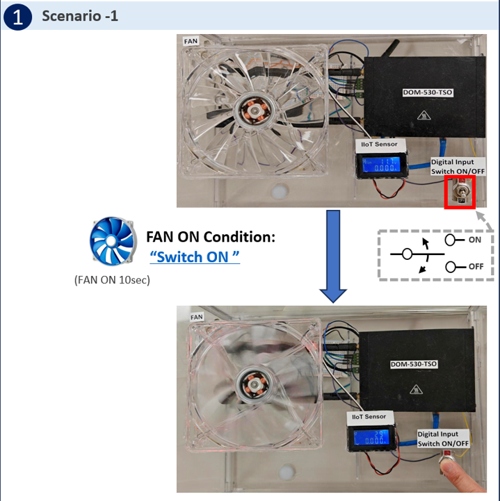
The DOM-530-TSO device on the left has a digital Input/Output interface that can be set to connect the DO output (DO-) to the fan and the pull-up load (DO+) to the VCC, and connect the DI to the switch button. When DI receives the "H" trigger event from the switch button, DO is activated and (DO-) output "High" turns on the fan.
Note: Before starting this configuration, please make sure the basic network settings of the D-Link M2M device are configured properly.
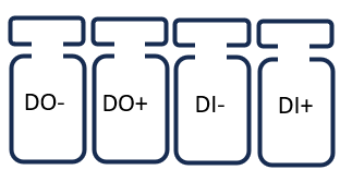
Please note that it is necessary to add an external pull-up load for the external power supply. The DO of the M2M device does not provide active voltage/current output function. The DO of the M2M DOM Series products is a dry contact.
This example is based on specific prerequisites and topology. D-Link does not guarantee compatibility with all IoT sensors.
DI/DO Configuration
Go to Service > SMS & Event > Configuration tab
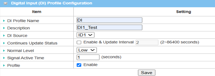
1. Digital Input Configuration:
You can click the Enable and Add buttons to configure the profile.
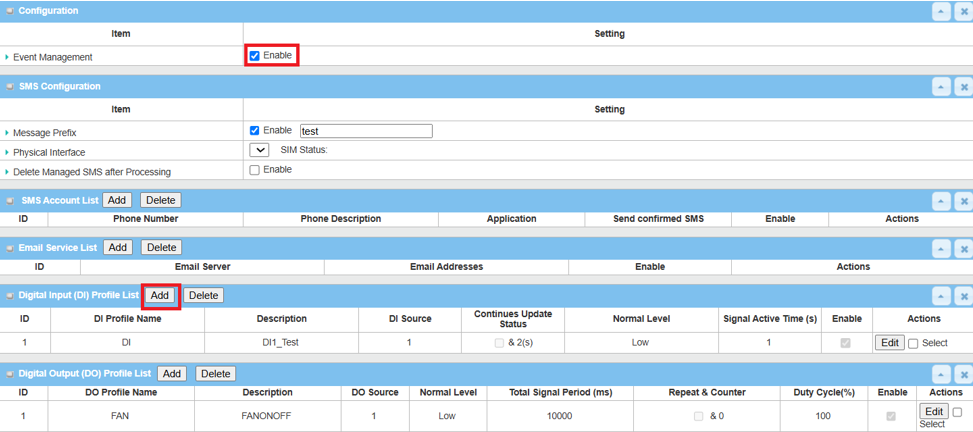
Here is the DI example shown below.
| Item | Description |
|---|---|
| DI Profile Name | Specify the DI Profile Name |
| Description | Specify a brief description for the profile |
| DI Source | Specify the DI Source as ID1 |
| Normal Level | Specify the Normal Level as Low |
| Signal Active Time | Specify the Signal Active Time for 1 second |
| Profile | Click Enable box to activate this profile setting |
| Save | Click the Save button to save the configuration |
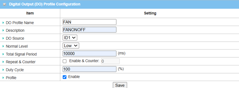
2. Digital Output Configuration:
You can click the Add button to configure the profile.

Here is the DO example, as shown below.
| Item | Description |
|---|---|
| DO Profile Name | Specify the DO Profile Name |
| Description | Specify a brief description for the profile |
| DO Source | Specify the DO Source from ID1 |
| Normal Level | Specify the Normal Level from Low |
| Total Signal Period | Specify the Total Signal Period for 10000 ms |
| Duty Cycle | Specify the Duty Cycle 100% for the Digital Output |
| Profile | Click Enable box to activate this profile setting |
| Save | Click the Save button to save the configuration |
DI Events Configuration
Go to Service > SMS & Event > Notifying Events tab
1. DI Event Profile Configuration:
You can click the Enable and Add buttons to configure the profile.
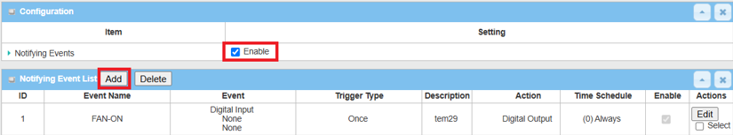
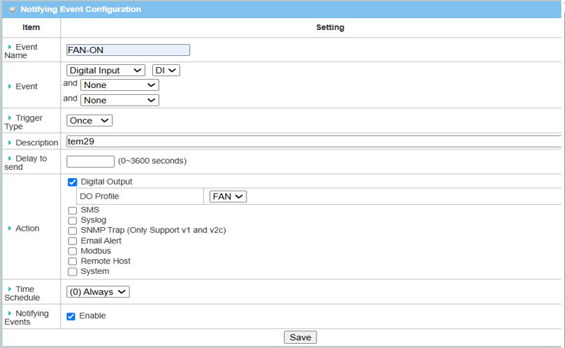
Here is the Notifying Events example, as shown below.
| Item | Description |
|---|---|
| Event Name | Enter a name for the event |
| Event | Select Digital Input as the event trigger and configure a DI profile first |
| Trigger Type | Select the triggering frequency: Period |
| Description | Enter a description for the event notification message |
| Action | Enter the “Digital Output” action for an event trigger |
| Notifying Events | Enable |
| Save | Click the Save button to save settings |
Test Result
Please set the fans and switches according to the above environment, then validate to ensure everything works as expected.
1. Expected Test Results:
Toggle the “Switch Button” to the ON position. The fan will turn on for 10 seconds.
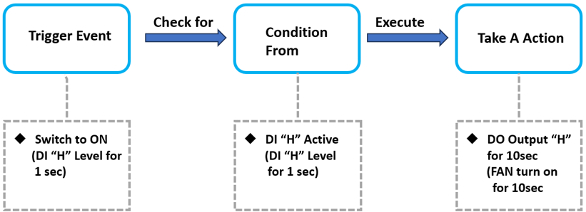
2. Test Results:
We take the DOM-530-TSO as an example to conduct the following test.
When DI receives an event (High for 1 second) from the "switch button", DO performs an action to turn FAN ON for 10 seconds.