Products
ProductsSolutionsApplications
Resources
Introduction
Internet Protocol Security (IPsec) is a suite of protocols designed to ensure the security of data transmitted over an IP network. It provides mechanisms for encrypting and authenticating IP packets, ensuring data confidentiality, integrity, and authenticity. Its flexibility and robust security features make it an essential tool for modern network security.
There are two common IPsec applications, IPsec Site-to-Site and IPsec Client-to-Site.
1. IPsec Site-to-Site: It creates a secure, encrypted tunnel between two or more networks, such as a corporate network and a branch office network. This allows organizations to connect their networks over the Internet securely.
2. IPsec Client-to-Site: It allows individual clients or the device behind NAT (private IP network) to securely connect to a corporate network over the Internet. This is also known as remote access VPN.
This article provides an example of how to configure IPsec functionality on D-Link M2M routers.
Please note that this example is based on specific prerequisites and topology. D-Link does not guarantee compatibility with all third-party platforms or clients.
Prerequisites
1. 2 x M2M devices: IPsec feature is applicable to the following models:
- DWM-313, DWM-530-T, DWM-550-G, DOM-550-TSO, DOM-550-GSO, DTM-550-G, DTM-570-GS
- At least one WAN interface of an M2M device must have a public IP address.
Please note that this prerequisite assumes both sites are Internet accessible.
Topology
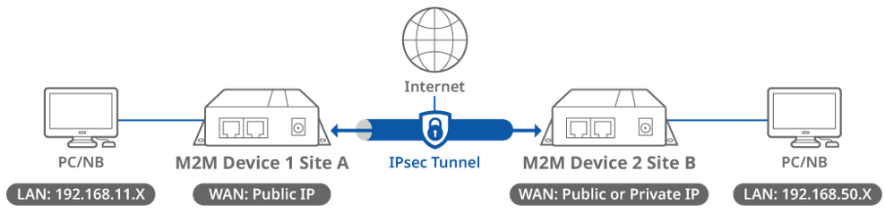
This topology diagram illustrates an IPsec VPN scenario. A D-Link M2M device at Site A has a public IP address on its WAN interface, while another D-Link M2M device at Site B has either a public or private IP address on its WAN interface. Once an IPsec tunnel is established between the two sites, the LAN subnet at Site A and Site B can communicate with each other. The packets transmitted through the IPsec tunnel are encapsulated and encrypted.
Before starting IPsec configuration, please make sure the basic network settings of the D-Link M2M device are configured properly.
Device 1 IPsec Configuration (Site A)
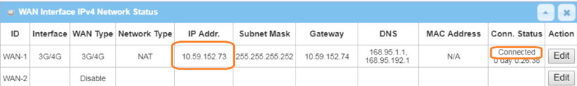
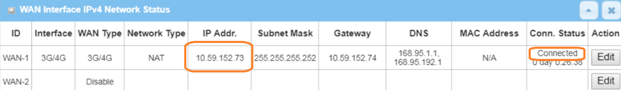
1. Before the IPsec configuration, please check the WAN interface status and make sure the M2M router/gateway WAN interface has already obtained a public IP address.
Go to Status > Basic Network > WAN & Uplink tab
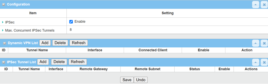
2. Enable IPsec setting: Go to Security > VPN > IPsec tab
Click the Enable box to activate the IPsec setting, and click Save button
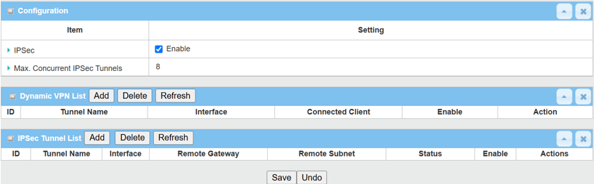
Please note that the specification of Max. Concurrent IPsec Tunnels varies across different D-Link M2M devices.
3. There are two IPsec configuration sections on the web UI.
- Dynamic VPN List: This section is for IPsec Client-to-Site.
- IPsec Tunnel List: This section is for IPsec Site-to-Site.
This example is based on the IPsec Site-to-Site topology shown above.
Click the Add button of the IPsec Tunnel List to create an IPsec policy for Site B.
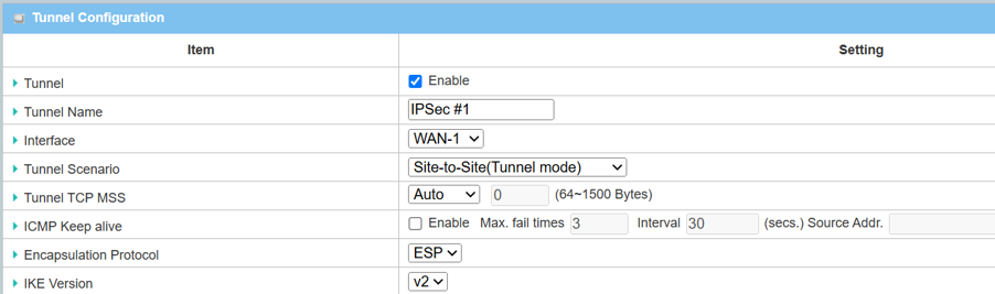
4. The Tunnel Configuration will appear, click the Enable box to enable the IPsec tunnel.
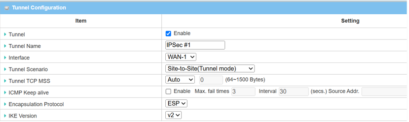
| Item | Description |
|---|---|
| Tunnel | Check the Enable box to activate the IPsec tunnel |
| Tunnel Name | Enter a tunnel name |
| Interface | Select the available WAN interface on which IPsec tunnel will be established |
| Tunnel Scenario | Select Site-to-Site (Tunnel Mode) from the drop-down menu |
| Tunnel TCP MSS | Select Auto from the drop-down menu |
| ICMP Keep Alive | Leave the Enable box unchecked to disable Keep Alive |
| Encapsulation Protocol | Select ESP from the drop-down menu |
| IKE Version | Select v2 from the drop-down menu |
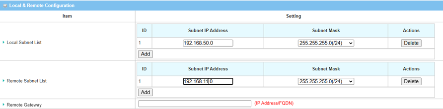
5. Fill in the local and remote subnet addresses to specify which subnets can be accessed.
5.1 If the WAN interface of device 2 in site B is a public IP address.
| Item | Description |
|---|---|
| Local Subnet List | Specify the local subnet IP address: 192.168.11.0 and Subnet Mask: 255.55.55.0(/24) based on this scenario |
| Remote Subnet List | Specify the Remote subnet IP address: 192.168.50.0 and Subnet Mask: 255.55.55.0(/24) based on this scenario |
| Remote Gateway | Specify the WAN public IP address of device 2 in site B |
5.2 If WAN interface of device 2 in site B is Private IP address.
| Item | Description |
|---|---|
| Local Subnet List | Specify the local subnet IP address: 192.168.11.0 and Subnet Mask: 255.55.55.0(/24) based on this scenario |
| Remote Subnet List | Specify the Remote subnet IP address: 192.168.50.0 and Subnet Mask: 255.55.55.0 based on this scenario |
| Remote Gateway | Specify 0.0.0.0 for device 2 in site B |
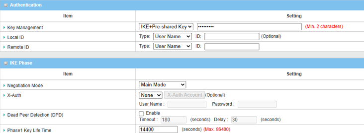
6. Setup Authentication and IKE parameters:
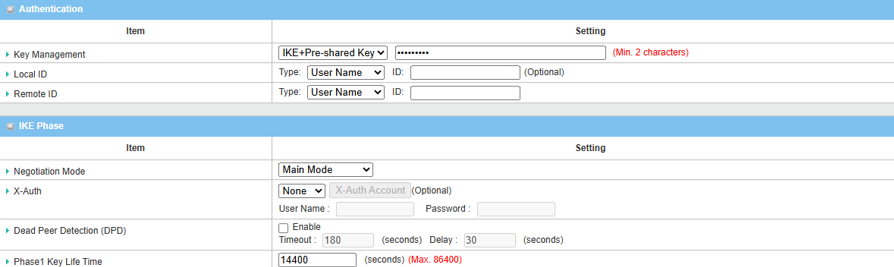
| Item | Description |
|---|---|
| Key Management |
Select IKE+Pre-shared Key from the drop-down menu, and fill in the pre-shared key Please note that the pre-share key must match for both device 1 and 2 |
| Local ID (optional) | Leave it as default setting |
| Remote ID (optional) | Leave it as default setting |
| Negotiation Mode | Select Main Mode from the drop-down menu |
| X-Auth | Select None from the drop-down menu |
| Dead Peer Detection | Uncheck the Enable box to disable DPD |
| Phase1 Key Lifetime | Leave 14400 default setting |
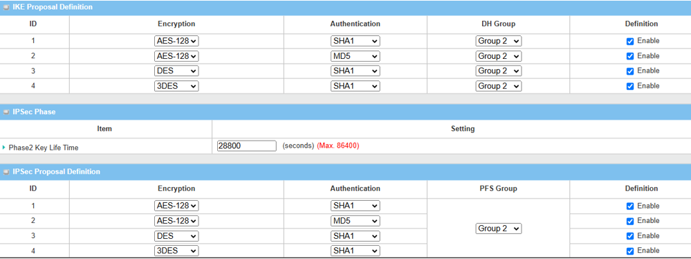
7. Setup Proposal Configuration
Please note that the configuration setting for both Device 1 and Device 2 must match.
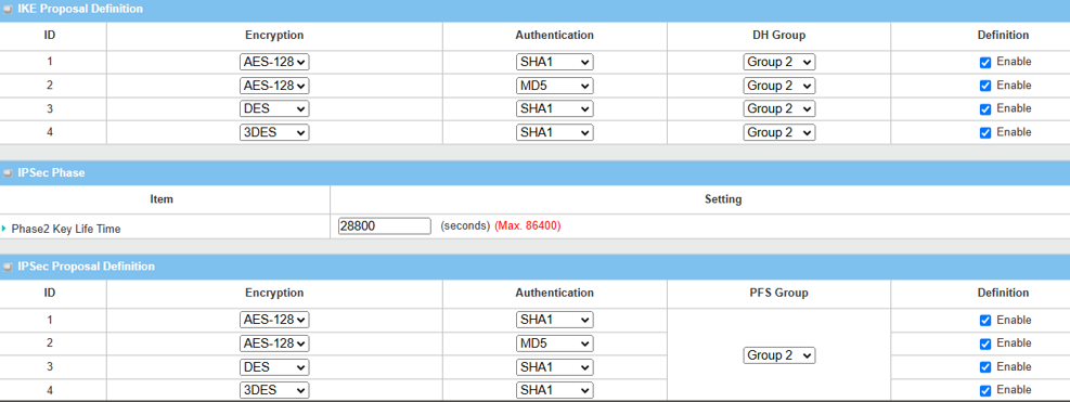
| Item | Description |
|---|---|
| IKE Proposal Definition |
Leave the Enable default setting on Web UI Encryption: AES-128 / DES / 3DES Authentication: SHA1 / MD5 DH Group: Group2 |
| Phase2 Key Lifetime | Leave 28800 default setting |
| IPsec Proposal Definition |
Leave the Enable default setting on Web UI Encryption: AES-128 / DES / 3DES Authentication: SHA1 / MD5 PFS Group: Group2 |
| Save | Click the Save button to save the settings |
Device 2 IPsec Configuration (Site B)
1. Before IPsec configuration, check the WAN interface status and make sure the M2M router/gateway WAN interface has already obtained a public IP address.
Go to Status > Basic Network > WAN & Uplink tab
2. Enable IPsec setting: Go to Security > VPN > IPsec tab
2.1 Click the Enable box to activate the IPsec setting, and click SAVE button
2.2 Click Add button of IPsec Tunnel List to create IPsec policy for Site A
3. The Tunnel Configuration will appear, click the Enable box to enable the IPsec tunnel.
| Item | Description |
|---|---|
| Tunnel | Check the Enable box to activate the IPsec tunnel |
| Tunnel Name | Enter a tunnel name |
| Interface | Select the available WAN interface on which IPsec tunnel will be established |
| Tunnel Scenario | Select Site-to-Site (Tunnel Mode) from the drop-down menu |
| Tunnel TCP MSS | Select Auto from the drop-down menu |
| ICMP Keep Alive | Leave the Enable box unchecked to disable Keep Alive |
| Encapsulation Protocol | Select ESP from the drop-down menu |
| IKE Version | Select v2 from the drop-down menu |
4. Fill in the local and remote subnet addresses to specify which subnets can be accessed.
| Item | Description |
|---|---|
| Local Subnet List | Specify the local subnet IP address: 192.168.11.0 and Subnet Mask: 255.55.55.0(/24) based on this scenario |
| Remote Subnet List | Specify the Remote subnet IP address: 192.168.50.0 and Subnet Mask: 255.55.55.0 based on this scenario |
| Remote Gateway | Specify the WAN public IP address of device 2 in site B |
5. Setup Authentication and IKE parameters
| Item | Description |
|---|---|
| Key Management |
Select IKE+Pre-shared Key from the drop-down menu, and fill in the pre-share key you set Please note that the pre-share key must match for both device 1 and 2 |
| Local ID (optional) | Leave it as default setting |
| Remote ID (optional) | Leave it as default setting |
| Negotiation Mode | Select Main Mode from the drop-down menu |
| X-Auth | Select None from the drop-down menu |
| Dead Peer Detection | Uncheck the Enable box to disable DPD |
| Phase1 Key Lifetime | Leave 14400 default setting |
6. Setup Proposal Configuration
Please note that the configuration settings for both Device 1 and Device 2 must match.
| Item | Description |
|---|---|
| IKE Proposal Definition |
Leave the Enable default setting on Web UI Encryption: AES-128 / DES / 3DES Authentication: SHA1 / MD5 DH Group: Group2 |
| Phase2 Key Lifetime | Leave 28800 default setting |
| IPsec Proposal Definition |
Leave the Enable default setting on Web UI Encryption: AES-128 / DES / 3DES Authentication: SHA1 / MD5 PFS Group: Group2 |
| Save | Click Save button to save the settings |
Test Result
Please configure the device according to the above environment, then validate to ensure everything works as expected.
From Device 1
1. Go to Status > Security > VPN tab
IPsec Tunnel Status table will display the tunnel information.

2. Go to Security > VPN > IPsec tab
The Status of IPsec Tunnel List displays "Connected" for Site B Device 2.

From Device 2
1. Go to Status > Security > VPN tab
IPsec Tunnel Status table will display the tunnel information.

2. Go to Security > VPN > IPsec tab
The Status of IPsec Tunnel List displays "Connected" for Site A Device 1.

From the client under the device 1 or 2
After the IPsec tunnel is established, you can also test the remote access from LAN clients by using ping <Remote LAN interface IP> or < Remote LAN device IP> within the remote subnet.